How does an aircraft fly ?


Have you ever wondered how an aeroplane takes off from the ground and achieves flight.whenever I see a plane in the sky ,I gaze at it till it vanishes from my sight ;wondering if I’ll ever get a chance to fly a plane.Lets have look into this interesting phenomenon through this post.

Aircraft can be classified as fixed wing and rotary wing aircraft.

Fixed wing aircraft: A fixed wing aircraft is an aircraft capable of flight using wings that generate lift due to the vehicle’s forward airspeed and the shape of the wings. Fixed-wing aircraft are distinct from rotary-wing aircraft in which wings rotate about a fixed mast and ornithopters in which lift is generated by flapping wings.

Rotary wing aircraft: A rotorcraft or rotary wing aircraft is a heavier-than-air flying machine that uses lift generated by wings, called rotor blades, that revolve around a mast. Several rotor blades mounted to a single mast are referred to as a rotor. The International Civil Aviation Organization (ICAO) defines a rotorcraft as “supported in flight by the reactions of the air on one or more rotors”. Rotorcraft generally include those aircraft where one or more rotors are required to provide lift throughout the entire flight, such as helicopters, cyclocopters, autogyros, and gyrodynes. Compound rotorcraft may also include additional thrust engines or propellers and static lifting surfaces.

Source: HowStuffWorks.com

For an aircraft to achieve flight,you have to exploit the four basic aerodynamic forces: lift, weight, thrust and drag. They seems to be like the four arms holding the plane in the air, each pushing from a different direction.

First, let’s examine thrust and drag. Thrust, whether caused by a propeller or a jet engine, is the aerodynamic force that pushes or pulls the airplane forward through space. The opposing aerodynamic force is drag, or the friction that resists the motion of an object moving through a fluid (or immobile in a moving fluid, as occurs when you fly a kite).

If you stick your hand out of a car window while moving, you’ll experience a very simple demonstration of drag at work. The amount of drag that your hand creates depends on a few factors, such as the size of your hand, the speed of the car and the density of the air. If you were to slow down, you would notice that the drag on your hand would decrease.

We see another example of drag reduction when we watch downhill skiers in the Olympics. Whenever they get the chance, they’ll squeeze down into a tight crouch. By making themselves “smaller,” they decrease the drag they create, which allows them to zip faster down the hill.

A passenger jet always retracts its landing gear after takeoff for a similar reason: to reduce drag. Just like the downhill skier, the pilot wants to make the aircraft as small as possible. The amount of drag produced by the landing gear of a jet is so great that, at cruising speeds, the gear would be ripped right off the plane.

For flight to take place, thrust must be equal to or greater than the drag. If, for any reason, the amount of drag becomes larger than the amount of thrust, the plane will slow down. If the thrust is increased so that it’s greater than the drag, the plane will speed up.

Lift and Weight : Every object on Earth has weight, a product of both gravity and mass. A Boeing 747-8 passenger airliner, for instance, has a maximum takeoff weight of 487.5 tons (442 metric tons), the force with which the weighty plane is drawn toward the Earth.

Weight’s opposing force is lift, which holds an airplane in the air. This feat is accomplished through the use of a wing, also known as an airfoil. Like drag, lift can exist only in the presence of a moving fluid. It doesn’t matter if the object is stationary and the fluid is moving (as with a kite on a windy day), or if the fluid is still and the object is moving through it (as with a soaring jet on a windless day). What really matters is the relative difference in speeds between the object and the fluid.

As for the actual mechanics of lift, the force occurs when a moving fluid is deflected by a solid object. The wing splits the airflow in two directions: up and over the wing and down along the underside of the wing.

The wing is shaped and tilted so that the air moving over it travels faster than the air moving underneath. When moving air flows over an object and encounters an obstacle (such as a bump or a sudden increase in wing angle), its path narrows and the flow speeds up as all the molecules rush though. Once past the obstacle, the path widens and the flow slows down again. If you’ve ever pinched a water hose, you’ve observed this very principle in action. By pinching the hose, you narrow the path of the fluid flow, which speeds up the molecules. Remove the pressure and the water flow returns to its previous state.

As air speeds up, its pressure drops. So the faster-moving air moving over the wing exerts less pressure on it than the slower air moving underneath the wing. The result is an upward push of lift. In the field of fluid dynamics, this is known as Bernoulli’s principle.

Lift Mechanism

How a plane files; video


Wankel Engines


The Wankel engine is a type of internal combustion engine using an eccentric rotary design to convert pressure into a rotating motion instead of using reciprocating pistons. Its four-stroke cycle takes place in a space between the inside of an oval-like epitrochoid-shaped housing and a rotor that is similar in shape to a Reuleaux triangle but with sides that are somewhat flatter. The very compact Wankel engine delivers smooth high-rpm power. It is commonly called a rotary engine, though this name applies also to other completely different designs. It is the only internal combustion engine invented in the twentieth century to go into production

The engine was invented by German engineer Felix Wankel. He received his first patent for the engine in 1929, began development in the early 1950s at NSU, completing a working prototype in 1957

 Working

In the Wankel engine, the four strokes of a typical Otto cycle occur in the space between a three-sided symmetric rotor and the inside of a housing. The expansion phase of the Wankel cycle is much longer than that of the Otto cycle. In the basic single-rotor Wankel engine, the oval-like epitrochoid-shaped housing surrounds a rotor which is triangular with bow-shaped flanks (often confused with a Reuleaux triangle, a three-pointed curve of constant width, but with the bulge in the middle of each side a bit more flattened). The theoretical shape of the rotor between the fixed corners is the result of a minimization of the volume of the geometric combustion chamber and a maximization of the compression ratio, respectively. The symmetric curve connecting two arbitrary apexes of the rotor is maximized in the direction of the inner housing shape with the constraint that it not touch the housing at any angle of rotation (an arc is not a solution of this optimization problem).

The central drive shaft, called the eccentric shaft or E-shaft, passes through the center of the rotor and is supported by fixed bearings. The rotors ride on eccentrics (analogous to cranks) integral to the eccentric shaft (analogous to a crankshaft). The rotors both rotate around the eccentrics and make orbital revolutions around the eccentric shaft. Seals at the corners of the rotor seal against the periphery of the housing, dividing it into three moving combustion chambers. The rotation of each rotor on its own axis is caused and controlled by a pair of synchronizing gears A fixed gear mounted on one side of the rotor housing engages a ring gear attached to the rotor and ensures the rotor moves exactly 1/3 turn for each turn of the eccentric shaft. The power output of the engine is not transmitted through the synchronizing gears. The force of gas pressure on the rotor (to a first approximation) goes directly to the center of the eccentric, part of the output shaft.

The best way to visualize the action of the engine in the animation at left is to look not at the rotor itself, but the cavity created between it and the housing. The Wankel engine is actually a variable-volume progressing-cavity system. Thus there are 3 cavities per housing, all repeating the same cycle. Note as well that points A and B on the rotor and e-shaft turn at different speed, point B moves 3 times faster than point A, so that one full orbit of the rotor equates to 3 turns of the e-shaft.

As the rotor rotates and orbitally revolves, each side of the rotor is brought closer to and then away from the wall of the housing, compressing and expanding the combustion chamber like the strokes of a piston in a reciprocating engine. The power vector of the combustion stage goes through the center of the offset lobe.

While a four-stroke piston engine makes one combustion stroke per cylinder for every two

Source:Wikimedia.org

rotations of the crankshaft (that is, one-half power stroke per crankshaft rotation per cylinder), each combustion chamber in the Wankel generates one combustion stroke per each driveshaft rotation, i.e. one power stroke per rotor orbital revolution and three power strokes per rotor rotation. Thus, power output of a Wankel engine is generally higher than that of a four-stroke piston engine of similar engine displacement in a similar state of tune; and higher than that of a four-stroke piston engine of similar physical dimensions and weight.

Wankel engines also generally have a much higher redline than a reciprocating engine of similar power output. This is in part because the smoothness inherent in circular motion, but especially because they do not have highly stressed parts such as a crankshaft or connecting rods. Eccentric shafts do not have the stress-raising internal corners of crankshafts. The redline of a rotary engine is limited by wear of the synchronizing gears[citation needed]. Hardened steel gears are used for extended operationon above 7000 or 8000 rpm. Mazda Wankel engines in auto racing are operated above 10,000 rpm. In aircraft they are used conservatively, up to 6500 or 7500 rpm. However, as gas pressure participates in seal efficiency, running a Wankel engine at high rpm under no load conditions can destroy the engine.

Applications

Mazda cars:Mazda has been a pioneer in developing production cars that use rotary engines. The RX-7, which went on sale in 1978, was probably the most successful rotary-engine-powered car. But it was preceded by a series of rotary-engine cars, trucks and even buses, starting with the 1967 Cosmo Sport. The last year the RX-7 was sold in the United States was 1995, but the rotary engine is set to make a comeback in the near future.

The Mazda RX-8 , a new car from Mazda, has a new, award winning rotary engine called the RENESIS. Named International Engine of the Year 2003, this naturally aspirated two-rotor engine will produce about 250

DRDO NISHANT UAV  uses an indegenously developed 55hp wankel engine . (http://en.wikipedia.org/wiki/DRDO_Nishant)

Advantages

There are several defining characteristics that differentiate a rotary engine from a typical piston engine.

  • Fewer Moving Parts

The rotary engine has far fewer moving parts than a comparable four-stroke piston engine. A two-rotor rotary engine has three main moving parts: the two rotors and the output shaft. Even the simplest four-cylinder piston engine has at least 40 moving parts, including pistons, connecting rods, camshaft, valves, valve springs, rockers, timing belt, timing gears and crankshaft.

This minimization of moving parts can translate into better reliability from a rotary engine. This is why some aircraft manufacturers (including the maker of Skycar) prefer rotary engines to piston engines.

  • Smoother

All the parts in a rotary engine spin continuously in one direction, rather than violently changing directions like the pistons in a conventional engine do. Rotary engines are internally balanced with spinning counterweights that are phased to cancel out any vibrations.

The power delivery in a rotary engine is also smoother. Because each combustion event lasts through 90 degrees of the rotor’s rotation, and the output shaft spins three revolutions for each revolution of the rotor, each combustion event lasts through 270 degrees of the output shaft’s rotation. This means that a single-rotor engine delivers power for three-quarters of each revolution of the output shaft. Compare this to a single-cylinder piston engine, in which combustion occurs during 180 degrees out of every two revolutions, or only a quarter of each revolution of the crankshaft (the output shaft of a piston engine).

  • Slower

Since the rotors spin at one-third the speed of the output shaft, the main moving parts of the engine move slower than the parts in a piston engine. This also helps with reliability.

Challenges

There are some challenges in designing a rotary engine:

One of the main challenge is the proper design of sealing.

The manufacturing costs can be higher, mostly because the number of these engines produced is not as high as the number of piston engines.

They typically consume more fuel than a piston engine because the thermodynamic efficiency of the engine is reduced by the long combustion-chamber shape and low compression ratio.

ABS-Antilock Braking System


Basically it Allows Braking and Steering

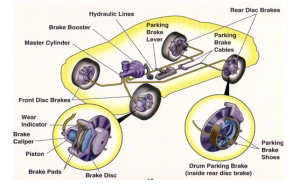
Also known as anti skid brakes, modern ABS systems electronically monitor the speed of the wheels and regulate the hydraulic pressure accordingly. The aim is to maximize braking power while preventing the wheels from locking and skidding.By keeping the wheels from skidding while you slow down, anti-lock brakes benefit you in two ways: You’ll stop faster, and you’ll be able to steer while you stop.

IMPORTANT  :

ALL THOSE WHO OWN OR DRIVE VEHICLES WITH “ABS” PLEASE NOTE

  • While operating a vehicle with ABS never pump the brakes. Doing so will make the ABS system ineffective. Always apply firm pressure.
  • Drivers may experience a pulsation/vibration in the brake pedal, or pedal kick back during an ABS stop. This is normal and not to be confused with a conventional brake pedal pulsation along with a buzzing sound
  • ABS system can maintain extremely high static pressure and must be disabled before attempting repairs. Normally pumping brake 20-30 times will release pressure

Based on studies made by insurance institute of road safety (IIHS) to determine if cars equipped with ABS are ­involved in more or fewer fatal accidents, vehicles equipped with ABS were overall no less likely to be involved in fatal accidents than vehicles without. The study actually stated that although cars with ABS were less likely to be involved in accidents fatal to the occupants of other cars, they are more likely to be involved in accidents fatal to the occupants of the ABS car, especially single-vehicle accidents.

The reason for this is that some people think that drivers of ABS-equipped cars use the ABS incorrectly, either by pumping the brakes or by releasing the brakes when they feel the system pulsing. Some people think that since ABS allows you to steer during a panic stop, more people run off the road and crash.

ABS brake system are either
  • Integrated :An integrated system has the master cylinder and control valve assembly made together.
  • Non integrated: A non integrated has the master cylinder and control valve assembly made separate
ABS brakes are either
1 Channel :1 channel ABS system controls the rear wheel together,it has only 1 speed sensor and control valve assembly.
3 Channel :3 channel ABS system control the rear wheel together and the front independently.3 channel ABS system have 3 speed sensor and 1 control module
4 Channel : There is speed sensors  and valves on all four wheels. With this setup, the controller monitors each wheel individually to make sure it is achieving maximum braking force.
Wheel Slippage is the relative speed between vehicle and the wheel.
If vehicle speed is faster than the wheel speed slippage is ve. And the wheel may become lock-up. If vehicle speed is slower than wheel speed. Wheel slippage is +ve.Positive wheel slippage occurs when a wheel is spinning.
In a diagonally split system brake system the left front and right rear brakes are controlled together. It offers an added safety value.

Four main components of an ABS system:

  • Speed sensors
  • Pump
  • solenoid Valves
  • Controller

Speed Sensors

The anti-lock braking system needs some way of knowing when a wheel is about to lock up. The speed sensors, which are located at each wheel, or in some cases in the differential, provide this information.

SPEED SENSORS

Valves

There is a valve in the brake line of each brake controlled by the ABS. On some systems, the valve has three positions:

  • In position one, the valve is open; pressure from the master cylinder is passed right through to the brake.
  • In position two, the valve blocks the line, isolating that brake from the master cylinder. This prevents the pressure from rising further should the driver push the brake pedal harder.
  • In position three, the valve releases some of the pressure from the brake.

Pump

Since the valve is able to release pressure from the brakes, there has to be some way to put that pressure back. That is what the pump does; when a valve reduces the pressure in a line, the pump is there to get the pressure back up.

PUMP

Controller

The controller is a computer in the car. It watches the speed sensors and controls the valves. It controller monitors the speed sensors at all times. It is looking for decelerations in the wheel that are out of the ordinary. Right before a wheel locks up, it will experience a rapid deceleration. If left unchecked, the wheel would stop much more quickly than any car could. It might take a car five seconds to stop from 60 mph (96.6 kph) under ideal conditions, but a wheel that locks up could stop spinning in less than a second.

The ABS controller knows that such a rapid deceleration is impossible, so it reduces the pressure to that brake until it sees an acceleration, then it increases the pressure until it sees the deceleration again. It can do this very quickly, before the tire can actually significantly change speed. The result is that the tire slows down at the same rate as the car, with the brakes keeping the tires very near the point at which they will start to lock up. This gives the system maximum braking power.

When the ABS system is in operation you will feel a pulsing in the brake pedal; this comes from the rapid opening and closing of the valves. Some ABS systems can cycle up to 15 times per second.

Anti-lock Brake Systems (ABS) working

When the brakes are applied, fluid is forced from the brake master cylinder outlet ports to the HCU(hydraulic control unit) inlet ports. This pressure is transmitted through four normally open solenoid valves contained inside the HCU, then through the outlet ports of the HCU to each wheel.The primary (rear) circuit of the brake master cylinder feeds the front brakes.
The secondary (front) circuit of the brake master cylinder feeds the rear brakes.
If the anti-lock brake control module senses a wheel is about to lock, based on anti-lock brake sensor data, it closes the normally open solenoid valve for that circuit. This prevents any more fluid from entering that circuit.The anti-lock brake control module then looks at the anti-lock brake sensor signal from the affected wheel again.If that wheel is still decelerating, it opens the solenoid valve for that circuit.Once the affected wheel comes back up to speed, the anti-lock brake control module returns the solenoid valves to their normal condition allowing fluid flow to the affected brake.The anti-lock brake control module monitors the electromechanical components of the system.Malfunction of the anti-lock brake system will cause the anti-lock brake control module to shut off or inhibit the system. However, normal power-assisted braking remains.Loss of hydraulic fluid in the brake master cylinder will disable the anti-lock system. The 4-wheel anti-lock brake system is self-monitoring. When the ignition switch is turned to the RUN position, the anti-lock brake control module will perform a preliminary self-check on the anti-lock electrical system indicated by a three second illumination of the yellow ABS wanting indicator.During vehicle operation, including normal and anti-lock braking, the anti-lock brake control module monitors all electrical anti-lock functions and some hydraulic operations.Each time the vehicle is driven, as soon as vehicle speed reaches approximately 20 km/h (12 mph), the anti-lock brake control module turns on the pump motor for approximately one-half second. At this time, a mechanical noise may be heard. This is a normal function of the self-check by the anti-lock brake control module.
When the vehicle speed goes below 20 km/h (12 mph), the ABS turns off.
Most malfunctions of the anti-lock brake system and traction control system, if equipped, will cause the yellow ABS warning indicator to be illuminated.

WATCH IT IN REAL ACTION(If your really busy just switch to 1:05)

Do follow us for more interesting article

FOUR WHEELER STEERING MECHANISMS


ACKERMANN STEERING MECHANISM

The most conventional steering arrangement is to turn the front wheels using a hand operated steering wheel which is positioned in front of the driver, via the steering column, which may contain universal joints (which may also be part of the collapsible steering column design), to allow it to deviate somewhat from a straight line. Other arrangements are sometimes found on different types of vehicles, for example, a tiller or rear wheel steering. Tracked vehicles such as tanks usually employ differential steering  that is, the tracks are made to move at different speeds or even in opposite directions to bring about a change of course

.

Rack and pinion unit mounted in the cockpit of an Ariel Atom sports car chassis.For most high volume production, this is usually mounted on the other side of this panel. Many modern cars use rack and pinion steering mechanisms, where the steering wheel turns the pinion gear; the pinion moves the rack, which is a linear gear that meshes with the pinion, converting circular motion into linear motion along the transverse axis of the car

sector rack and pinion

. This motion applies steering torque to the swivel pin ball joints that replaced previously used king pins of the stub axle of the steered wheels via tie rods and a short lever arm called the steering arm.The rack and pinion design has the advantages of a large degree of feedback and direct steering “feel”. A disadvantage is that it is not adjustable, so that when it does wear and develop lash, the only cure is replacement.

recirculation ball

Older designs often use the recirculation ball mechanism, which is still found on trucks and utility vehicles. This is a variation on the older worm and sector design; the steering column turns a large screw (the “worm gear”) which meshes with a sector of a gear, causing it to rotate about its axis as the worm gear is turned; an arm attached to theaxis of the sector moves the Pitman arm, which is connected to the steering linkage and thus steers the wheels. The recirculation ball version of this apparatus reduces the considerable friction by placing large ball bearings between the teeth of the worm and those of the screw; at either end of the apparatus the balls exit from between the two pieces into a channel internal to the box which connects them with the other end of the apparatus, thus they are “recalculated”.The recalculating ball mechanism has the advantage of a much greater mechanical advantage, so that it was found on larger, heavier vehicles while the rack and pinion was originally limited to smaller and lighter ones; due to the almost universal adoption of  power steering, however, this is no longer an important advantage, leading to the increasing use of rack and pinion on newer cars

POWER STEERING

Power steering assists the driver of an automobile in steering by directing a portion of the vehicle’s power to traverse the axis of one or more of the road wheels. As vehicles have become heavier and switched to front wheel drive, particularly using negative offset geometry, along with increases in tire width and diameter, the effort needed to turn the steering wheel manually has increased often to the point where major physical exertion is required. To alleviate this, auto makers have developed power steering systems: or more correctly power-assisted steering on road going vehicles there has to be a mechanical linkage as a fail safe. There are two types of power steering systems  hydraulic and electric/electronic.

POWER STEERING

A hydraulic-electric hybrid system is also possible.A hydraulic power steering (HPS) uses hydraulic pressure supplied by an engine-driven pump to assist the motion of turning the steering wheel. Electric power steering(EPS) is more efficient than the hydraulic power steering, since the electric power steering motor only needs to provide assistance when the steering wheel is turned,whereas the hydraulic pump must run constantly. In EPS, the assist level is easily tune able to the vehicle type, road speed, and even driver preference. An added benefit is the elimination of environmental hazard posed by leakage and disposal of hydraulic power steering fluid. Also in the event of the engine cutting out, assist will not be lost where as hydraulic will stop working, as well as making the steering doubly heavy as the driver has to turn the power-assist mechanism on top of the steering system itself.

 SPEED SENSITIVE STEERING

A Interesting and innovative outgrowth of power steering is speed sensitive steering, where the steering is heavily assisted at low speed and lightly assisted at high speed. The auto makers perceive that motorists might need to make large steering inputs while maneuvering for parking, but not while traveling at high speed. The first vehicle with this feature was the CitroënSM with its Diravi layout, although rather than altering the amount of assistance as in modern power steering systems, it altered the pressure on a centering cam which made the steering wheel try to “spring” back to the straight-ahead position.Modern speed-sensitive power steering systems reduce the mechanical or electrical assistance as the vehicle speed increases, giving a more direct feel. This feature is gradually becoming more common

TORSEN-torque sensing traction


The Torsen dates back to 1983. Since then it has been used by various carmakers, including Audi and Hummer. The Torsen multiplies what torque is available from the axle that is starting to spin or lose traction, and sends it to the slower-turning axle with better traction. The gears allow a torque-bias ratio of 4:1, which means they can deliver four times as much power to the non slipping axle than can be supported by the slipping axle. One big advantage of Torsen systems is that because they are purely mechanical, they react very quickly to slip.TORque SENsing traction

Most often, loss of control is compounded by vehicle’s inability to recover or to cope with hazardous road surface. The TORSEN Traction differential increases the margin of safety by improving a vehicles’s capability to manage unexpected road conditions. TORSEN works continuously, providing a more stable and controllable driving platform, which could help to reduce the chance of a potential accident before it can occur.

In normal driving conditions, power from the engine is equally distributed to both the axles resulting in equal traction between both the wheels. while this configuration is ideal for normal straight line driving,its unsuitable for variable road surfaces like ice, snow, mud etc..

Loss of traction causes wheel spin, a potentially dangerous condition on slippery roads. unlike conventional speed sensing LSD’s(Limited Slip Differential),TORSEN Traction Differentials respond instantly, shifting power to the wheel with the most traction.There is no wheel spin, lag time or momentary loss of traction.

torque distribution

How TORSEN Traction Differential works

The TORSEN Traction differential is designed to outperform conventional differentials. It is an advanced and highly efficient traction control system engineered to effectively manage power (torque) distribution and traction management. Unlike limited-slip differentials, the TORSEN Traction Differentials has no clutches to slip or wear out. Instead. it is an on-demand, torque sensing, torque biasing system.The driven axles are directly coupled through patented INVEX,EQUIVEX

INVEX

 
 EQUIVEX

PLANETARY GEARS

, or planetary Helical gears allowing multifunction capabilities in one integral unit. Torque transmission,torque biasing and differentiation, essential functions for effective traction control, are performed simultaneously,all in one compact unit. For center applications, front or rear biased torque splits are also possible. Because it is a solid, no-slip geared system, the TORSEN differential will perform for the life of the vehicle.